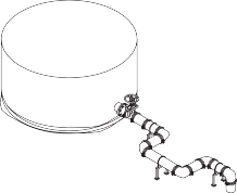
3. Absorption of distortion
With the use of an assembly as shown below, ground sinking or movement around a tank or reservoir can be
effectively absorbed, avoiding damage to the tank, reservoir and or the piping system.
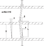
4. Absorption of inter-floor deflection
α = H x 1/150 = 4000 x 1/150 = 27mm
Risers of high-rise flexible
structure buildings are
subjected to lateral sways
(inter-floor deflection)
when an earthquake occurs.
If we assume the inter-floor
deflection (α) as 1/150 and
the floor height (H) as 4
meters, the estimated interfloor deflection (α) will be.
If we use a 200mm (8’’) 7707 coupling for each floor, the maximum deflection (β) that each coupling can accommodate will be.
β = L x tan θ = 4000x 0.02915 = 4.56’’ = 116mm (θ = 1.67°)
The example shows a flexible coupling would be
sufficient enough to absorb this scale of seismic sways.
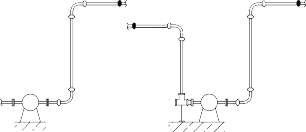
5. Absorption of misalignment
As shown in the diagram, each branch connecƟon to the free riser will be subjected to serious shearing forces as pressure thermal movement increases. By using two flexible couplings, you can solve this problem.
5. Absorption of misalignment
As shown in the diagram, each branch connection to the
free riser will be subjected to serious shearing forces as
pressure thermal movement increases. By using two flexible
couplings, you can solve this problem.


TYPICAL APPLICATIONS - FLEXIBLE
COUPLINGS - SPRINKLER SYSTEMS
(NFPA 13)
1. Flexible couplings for main risers and branch line riser
2. Adjustment of misalignment
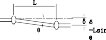
When a straight run has need for a slight adjustment of
alignment on the jobsite as shown in the diagram, you can
accomplish this with the use of two flexible couplings. The
following table shows the deflecƟon value (θ) of the Lede
7705 flexible couplings.

6. Curved layout
R = L
(2 x tan θ/2)
μ = α x L x ΔΤ
With Lede flexible couplings you can design a slowly
curved layout for a system along a curved tunnel, winding
road or curved building.
As the liner expansion coefficient for steel (α) is 1.2 x10⁻⁵,
you can use table above to determine the thermal expansion.
Example:
The thermal expansion of a 5.5 meter standard length or pipe (μ) is within the allowance (= max. pipe end separation) of a flexible coupling. In other words, if you use
a coupling for each pipe length of 5.5 meters, the coupling will accommodate the thermal expansion or contraction expected to take place for a 40°C temperature change.
When you calculate the necessary number of coupling (N) for an anchored system, you should place a clearance of N x E x 1/2 as a safety factor.
Whether it is thermal expansion, contraction, or a combination thereof, the system requires suitable anchor installations with properly space alignment guides and
weight support devices. Where and when larger thermal movement is anticipated, you should use supplementary expansion joint(s).
For installers who use the imperial units of measure, the following table will be more convenient.
Pipe size: 100mm (4’’)
Max. pipe end separation (E): 3.2mm
Pipe length (L): 5.5M
Temperature difference (ΔT): 40°C (+5°C to +45°C)
7. Absorption of Thermal Stress
Thermal stress is caused by changes in temperature, resulting in either expansion or contraction. With the use of Lede flexible couplings you can design your system to
accommodate such movement without the need for costly expansion joints. The thermal expansion or contraction (μ)
is determined by the length of pipe (L) and temperature difference (ΔT).
Example: When using model 7705 100mm (4’’) couplings for the layout as shown in the diagram, the max. allowed deflection (θ) of the coupling is 3.4°, and the pipe length (L) is 5.5 meters, the radius of curvature (R) will be 92.7 meters. (where: R is radius of curvature, L is pipe length, and θ is max. allowed deflection of a coupling)
1 0.0120.070.120.240.360.4850.060.330.61.21.82.4100.120.661.22.43.64.8200.241.32.44.87.29.6300.3623.67.21115400.482.64.89.61420500.63.36121824600.7247.2142229700.844.68.4172534800.965.39.6192939Temperature
Difference
ΔT
(℃)Pipe Length L (meters)Thermal Expansion (millimeters)1 5.5* 10 20 30 40Thermal Expansion (Metric)
* 5.5 meters is the standard length of commercial carbon steel pipe.
0-0.10-0.20-0.29-0.4925-0.06-0.13-0.19-0.3250-0.03-0.06-0.08-0.147000001000.050.090.140.231250.080.170.250.421500.120.240.370.611750.160.320.480.802000.200.400.590.992250.240.480.731.21Temp (°F) Pipe Length L (feet)Thermal Expansion between 70°F
and indicated temperature (inch)20 40 60 100Thermal Expansion (Imperial)
* Coefficient of thermal expansion of steel pipe = 6.33 in/in, °F x 10-6
μ = α x L x ΔT = 1.2 x 10-5 x 5500 x 40 = 2.64mm
TYPICALAPPLICATIONS|4
As the liner expansion coefficient for steel (α) is 1.2 x10⁻⁵,
you can use table above to determine the thermal
expansion.
Example:
The thermal expansion of a 5.5 meter standard length or pipe (μ) is within the allowance (= max. pipe end
separation) of a flexible coupling. In other words, if you use a coupling for each pipe length of 5.5 meters, the coupling will accommodate the thermal expansion or contraction expected to take place for a 40°C temperature change.
When you calculate the necessary number of coupling (N) for an anchored system, you should place a clearance of N
x E x 1/2 as a safety factor.
Whether it is thermal expansion, contraction, or a combination thereof, the system requires suitable anchor
installations with properly space alignment guides and weight support devices. Where and when larger thermal
movement is anticipated, you should use supplementary expansion joint(s).
For installers who use the imperial units of measure, the following table will be more convenient.
Adres
Acıbadem cad. A2 Blok D4 No:73
Kadıkoy, Istanbul
İletişim
+90-216-3278505
info@teknoyangin.com.tr
Tekno Yangın ve Havalandırma Sistemleri Ltd.Şti.